Connecting the HyDip LCD
Opening the LCD display
To get access to the connectors on the LCD you will need to open the case and reveal the circuit board (PCB).
The LCD case is made up of:
- an all-in-one top/back/base plate
- a front plate, with the display glass and a wake up button
- a cable gland end plate
- a buzzer end plate.
First remove the cable gland end plate and the buzzer end plate:
- Using a small flat-bladed screwdriver pick out the two weather resistant caps on each end plate.
- Using a T10 hex screwdriver remove the screws from each end plate.
- Carefully release each end plate:
- The cable gland end plate should just come away. Be careful not to drop the weatherproof gasket.
- The buzzer end plate will be connected by a short cable. Pushing from the cable gland end, slide the PCB out a few centimetres to reveal the buzzer connector, and unclip it to release the end plate and gasket.
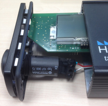
You cannot slide the PCB further than a few cmThe PCB is connected by a wire to the front plate. This means that you cannot connect the LCD just by sliding out the PCB, although you can get access to the DIP switch pads.
Carefully pop out the front plate:
- lay the LCD on its back
- place two fingers behind each end of the base plate
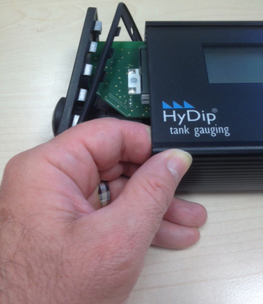
- Firmly press the edge of the front plate with your thumbs while restraining the base plate with your fingers.
- Apply upward pressure with the sides of your fingers to pop it out.
You have to be careful lifting the front plateRemember as you lift the front plate off that it is connected to the PCB by a wire, which may be quite short. Pulling the wire will damage the LCD.
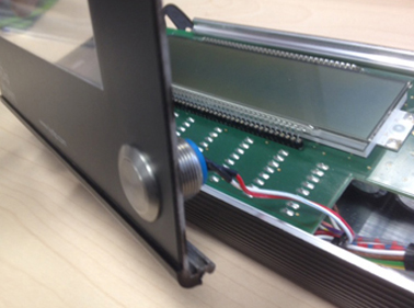
Note the wire connecting the front plate to the PCB
Now slide the PCB carefully out of the casing, allowing the front plate to go with it.
You can now see the connection pins on the underside.
Connecting the LCD to the HTG or HFT device
There are three connections to consider when connecting an LCD to a HyDip device:
- Power
- Signal
- Wake (up)
An overview of the connections from the HyDip device to the LCD is shown in the diagram and table, followed by details of each aspect.
We suggest you use these colours of wire for consistency. Don’t forget: all wiring must be threaded through the weatherproof gland, end plate and gasket before connecting.
.jpg)
HyDip | Wire colour | LCD |
|---|---|---|
BATT | Red | VPWR |
GND | Black | VGND |
D-A | Green | 485A |
D-B | Yellow | 485B |
D-GND | Black | GND |
IN1+ | Blue | WAKE |
IN1- | Black | GND |
Note that all ground wires can be linked.
Power#
A 6.2V sealed lead acid battery should be connected to the HyDip device, using a cable plugged into the BATT / GND connector.
To connect the LCD to this power supply, just run a lead from the VPWR and VGND pins to the HyDip device, and double up on the BATT / GND connector plug.
Signal
To send a tank level signal to the LCD, run a lead from the D-A, D-B and D-GND connector on the HyDip device to the 485A, 485B and GND pins on the LCD. Any GND pin on the LCD will work.
Wake up
The IN1 connector on the HyDip device is used to wake it up, for example by connecting it to a door reed switch, or the push button on the LCD display.
Connect IN1+ to the WAKE pin on the LCD, and IN1- to a GND pin.
Connecting multiple LCDs
You may site LCDs on up to four tanks from one HyDip HFT device. You can use a star arrangement to connect each LCD separately, or daisy chain to the next LCD from the corresponding pins on the adjacent terminal block as shown here:
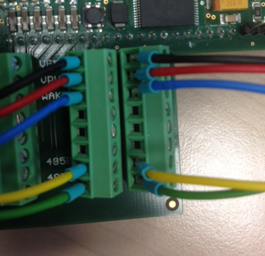
Wires from the VGND, VPWR, WAKE, 485A and 485B pins (on the left in this picture) run to the HyDip device. The unlabelled row of pins (on the right in this picture) can be used to run a cable to an LCD display on another tank.
You will need to set the DIP switches to identify the second, third and fourth LCD.
Setting DIP switches
The LCD has functions that can be changed using the row of six DIP switches.
For practical purposes, these only need to be turned on:
-
to suppress the overfill buzzer and any external horn attached to it, or
-
to set an identifying address when installing more than one LCD.
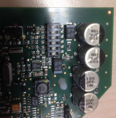
There is one set of DIP switches. Here you can see them numbered 1 to 6. All are in the OFF position in this picture.
You can access the DIP switches by removing the PCB as instructed, or simply by sliding the PCB out a few centimetres at the buzzer end.
When you look at the DIP switches you’ll see them numbered 1 - 6. Off is the side with the numbers; the other side has a label saying ‘ON’.
Special functions, DIP 6, DIP 4 and DIP 3
DIP numbers 6, 4 and 3 are reserved for special functions and should be set to the OFF position.
Un-suppressing the overfill alarm: DIP 5
The overfill buzzer remains quiet if a sensor in the tank is not detecting an overfill.
If the tank goes above the safe level the buzzer sounds. If there is no sensor in the tank, the signal reads the same as if there was an overfill, and the buzzer will sound.
The LCD is shipped with the alarm suppression on DIP 5 set to on. To enable the overfill alarm, use a small screwdriver to click DIP 5 to the OFF position.
Setting up two, three or four tanks: DIP 2 and DIP 1
The HyDip can collect level readings from up to four tanks. It is possible to mount an LCD on each of these (see above), but each LCD must be assigned an address to identify it as tank 1, 2, 3 or 4.
To do this, set the binary number for 0, 1, 2 or 3 (00, 01, 10 or 11) using DIP switches 2 and 1 as shown in the table below. Use a small screwdriver to click the switch across.
Tank no. | DIP 2 | DIP 1 | Notes | Binary (binary) | Binary (decimal) |
|---|---|---|---|---|---|
1 | Off | Off | This is the position for the first or only LCD. | 00 | 0 |
2 | Off | ON | If this is an LCD for Tank 2, simply switch DIP 1 on. | 01 | 1 |
3 | ON | Off | If this is an LCD for Tank 3, simply switch DIP 2 on. | 10 | 2 |
4 | ON | ON | If this is an LCD for Tank 4, switch DIP 1 and DIP 2 on. | 11 | 3 |
Reassembling the LCD display
Before you reseal the LCD unit, check that the DIP switches are in the correct position (see above).
To reassemble the LCD:
First, lay the main casing on its back, checking underneath to make sure the label will end up the right way up near the bottom.
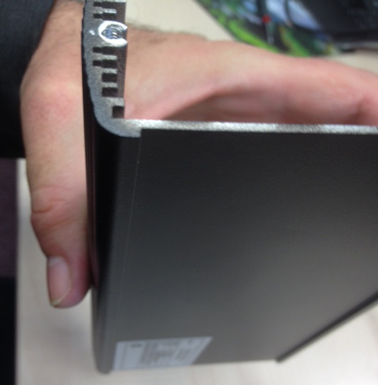
Next, carefully slide the PCB back into position. Make sure that:
- the board goes in pin side down and display side up
- the front plate will end up with the button bottom right
- you use the slots just above the screw holes.
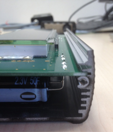
Note the correct slot is just above the screw hole
Now line the front plate up exactly and ease it back on, using a little pressure from your fingers and thumbs in a reversal of the removal movement. Note that it doesn’t slide to adjust easily.
Sliding the PCB out a little, plug the buzzer cable back in, ensuring the weatherproof gasket hasn’t been forgotten. Slide the PCB carefully back into place.
Screw the end plates back into position, ensuring that you:
- attach the mounting bracket with the screws
- tighten the weatherproof cable gland
- reapply the weatherproof screw caps.
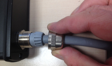
Make sure you have threaded both parts of the cable through the weatherproof gland before you attach the wires. Tightening the metal screw cap creates a weatherproof seal.
Updated 12 months ago
